Direct Fire Coil Models
All models with Direct Fire ignition feature coils with internal igniter modules.
Dwell Time
Distributor Models
Direct Fire Models
DBW Throttle System
Models that have the ETCS-i throttle system are not supported by Haltech.
Models that use a normal cable throttle, or have full DBW (no throttle cable) are supported.
All variants use a single throttle body.
DBW Throttle Wiring
Position Sensors
| Pin |
Description |
Haltech Connection |
| 1 |
5V+ |
5V+ |
| 2 |
TPS2 |
AVI3 |
| 4 |
TPS1 |
AVI2 |
| 5 |
Signal Ground |
Signal Ground |
Drive Motor
| Pin |
Haltech Connection |
| 3 |
DBW1 |
| 6 |
DBW2 |
DBW Accelerator Pedal Position Sensors Connection
| Pin |
Description |
Haltech Connection |
| 1 |
Signal Ground |
Signal Ground |
| 2 |
APP2 |
AVI5 |
| 3 |
Signal Ground |
Signal Ground |
| 4 |
5V+ |
5V+ |
| 5 |
APP1 |
AVI4 |
| 6 |
5V+ |
5V+ |
Throttle Position Sensor
Early 1UZ models use a cable throttle with a conventional throttle position sensor.
This engine uses a cable operated throttle body with a position sensor.
OEM Wiring
|
Haltech Wiring
|
A
|
5V+ |
B
|
Signal (Spare AVI) |
C
|
Closed Throttle Switch - NOT USED |
|
D
|
Signal Ground |
MAP Sensor
These engines do not come with a MAP sensor.
Use the internal MAP sensor that comes with your ECU. For higher boost levels an external MAP sensor should be used instead, connected to a spare AVI.
Variable Cams
Engines with VVTi have Toyotas Gen 3 continuously variable cam control. The ECU uses a 3x tooth cam sensor on each inlet cam to know the position of the camshafts relative to the crank position. A duty signal is sent to each cam control solenoid. The solenoid regulates oil pressure being fed into the cam control mechanism to advance or retard the cams to their target position using closed-loop. They cannot be sent to a specific position using open loop.
Idle Valve
The cable throttle 1UZ engine uses a Stepper Motor idle valve controlled via the Stepper Outputs. It will not work on Elite 550/750/950 ECU models.
Pin
|
Haltech Connection
|
| A |
Stepper 4
|
| B |
12V+ Ign Switch or No Connection |
| C |
Stepper 3 |
| D |
Stepper 1 |
| E |
12V+ Ign Switch or No Connection |
| F |
Stepper 2 |
Drive Type: Low Side if 12V+ is connected. Both if 12V+ is not connected
Steps:240 Speed:75
Coolant Temperature
Located near the RHS Distributor.
Wiring is not polarity sensitive
Pin
|
Haltech Connection
|
| 1 |
Any Spare AVI* |
| 2 |
Signal Ground |
An AVI with a selectable Pullup should be used. If not and external 1k pullup to 5V should be connected.
Calibration: Use "Temperature - xxxxxxx.cal"
Created for Haltech ECUs using a 1k pullup to 5V
Air Temp
An air temperature sensor is incorporated in the MAF Sensor. If the MAF is deleted then an external Air Temperature Sensor needs to be installed in the intake, preferably in the plenum near to where the MAP sensor connects.
Haltech 1/8" NPT Air Temp Sensor
Wiring is not polarity sensitive.
Calibration: Use "Temperature - GM Air Sensor.cal"
Created for Haltech ECUs using a 1k pullup to 5V
Knock Sensor
The 1UZ has 2x resonant style single-wire knock sensors located in the intake valley near the starter motor. Although they can be used they are not as reliable as newer donut style resonant sensors.
Recommended Knock Sensor. Haltech HT-011100
MAF Sensor
Although most users of Haltech ECUs will be deleting the MAF, it is possible to use a MAF if you prefer. It also incorporates an Air Temperature Sensor, so if the MAF Sensor is removed a new Air Temperature Sensor must be installed in the intake.
1UZ Early
The early 1UZ use a Frequency based MAF Sensor. It is not a normal 0-5V signal.
Pin
|
OEM Wire Colour
|
Connection
|
1
|
Brown
|
Signal Ground |
2
|
Yellow/Black
|
Air Temperature (AVI) |
3
|
Yellow/Green
|
MAF Signal (SPI or DPI)
|
4
|
Blue/Red
|
5V+ |
|
5
|
Brown
|
Signal Ground
|
2UZ
|
Pin
|
Description
|
Haltech Connection
|
|
1
|
B+ (Power)
|
12V+
|
|
2
|
E2G (MAF Ground)
|
Signal Ground
|
|
3
|
VG (MAF Signal)
|
SPI or DPI
|
|
4
|
THA (Air Temp Signal)
|
AVI |
|
5
|
E2 (Air Temp Ground)
|
Signal Ground
|
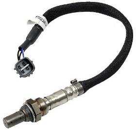
O2 Sensors
1UZ engines have 4x Narrowband 4-wire O2 sensors. Narrowband sensors are not useful for tuning and are used primarily for catalytic converter efficiency.
O2 Sensor Wire Colours
|
Haltech Connection
|
Black (Signal)
|
AVI 1 or AVI 6
|
| Grey |
Signal Ground (Black/White) |
| White |
12V+ Switched |
| White |
Chassis Ground (not Signal Ground) or Spare Output |
It is possible for the ECU to supply a duty signal to the Heater Ground, with many OEM ECUs doing this. Haltech ECUs can also perform this task and a spare Injector or Stepper Output should be used.
O2 Sensors can use various wattage heater elements, with 12W and 18W being common. For 18W units it is advised to not supply more than ~50% duty to prevent excessive current being applied to the ECU output.
For post-cat sensors it is advised to not enable the heater ground control until the engine is at full operating temperature. This is to prevent moisture in the exhaust from a cold started engine from damaging the heater element. Many OEM strategies involve not enabling the heater until the engine have been driven above a set speed for a set amount of time.
Adding a Haltech Wideband Kit (highly recommended)
For correct operation a Haltech WB2 kit is highly recommended for this application, with the provided 4.9 sensors replacing the pre-cat sensors. Swapping the sensors is accessed only from below the vehicle. Sensors use a 22mm socket or spanner to remove and replace.
Vehicle Speed Sensor
This engine uses a Reluctor Vehicle Speed sensor.
Reluctor Speed Sensor Wiring
| OEM Wiring |
Description |
| Signal + |
Any Spare SPI |
| Signal - |
Signal Ground |
Injector Data
Early 1UZ engines have only 4x injector outputs from the OEM ECU, run as semi sequential. They are joined in the OEM wiring as 1+7, 2+8, 3+5, 4+6
1UZ VVTi and all 2UZ and 3UZ engines have sequential injection
Flow
The injector flow rate is measured with the injectors held wide open at 100% duty. For fuel systems with a fixed regulator pressure (often returnless systems) that is not referenced to manifold pressure the flow needs to be mapped over Manifold Pressure for accurate tuning.
Early 1UZ-FE have 240cc/min injectors.
Dead Time
When an injector is commanded to open for a certain amount of time, the dead time is the amount of time the injector is not actually open during this period. It covers the time to energise the solenoid and begin to open and the time to close as well. There are also transient periods during which the injector is opening and closing where fuel flow is not at full capacity so this lost peak flow period is also taken into account.
OEM ECU Information
There are a number of different ECU connectors found on the 1UZ, 2UZ and 3UZ ECUs.
1UZ-FE ECU
LS400 (MY98-00)
Soarer UZZ30
2UZ-FE ECU

Leave a comment